This popular geometrical block puzzle involves packing the twelve possible pentominos (which are like dominos but occupying five unit cells each instead of two) into a rectangular grid. For example, here is one solution using a 10 x 6 grid:
There are 18,712 unique ways to pack the pentominos into a 10 x 6 grid.
If we exclude the trivial symmetries of rotating the board 180 degrees or flipping it about the horizontal or vertical axes, there are 2,339 unique solutions, a factor of 2 x 2 x 2 less.
Six of the pentominos are chiral in that if they are flipped over they take on different unique shapes that pack differently. If we do not allow flipping pentominos, and also exclude trivial symmetries, the number of solutions drops significantly (to 46 using the chiral orientations shown in the title image).
There are various sets of pentominos and packing trays available for 3D printing on Thingiverse (like this or this) . Typically the surface quality is different on the top vs. bottom of 3D printed pieces, so one might consider those to be physically flippable but aesthetically unflippable.
Three other grid sizes (12 x 5, 15 x 4 and 20 x 3) are also possible since the total size must be 60 units.
The number of solutions in each case are shown below, but the right column applies for the particular set of pentomino orientations shown in the left picture, and might change if any are flipped.
| Box size | Flip | No Flip |
| 10 x 6 | 2,339 | 46 |
| 12 x 5 | 1,010 | 36 |
| 15 x 4 | 368 | 15 |
| 20 x 3 | 2 | 0 |
It is not easy to find a solution, nor to find a general strategy for solving it by hand. Solving it by luck is not particularly entertaining or satisfying either.
I took it as a challenge to see how fast I could write a program to find the solutions, but it morphed into a larger effort refining multiple solving methods and programs. And then far more time could be spent delving into the many additional variations of the puzzle; for example:
But I had to stop somewhere. The results of my labors are here on Github.
I’ve played with boolean satisfiability solvers before and found them fascinating. If you can express a problem as a single boolean equation, then you can just run a general program that solves boolean equations, translate the equations back to the problem and you’ve got an answer.
The catch is that the equation usually ends up with hundreds to thousands of variables, involved in thousands to tens of thousands of boolean terms, so you need to write a program to generate it. Typically it must also be written in a simple standard form called “conjunctive normal form” (CNF), where the whole equation is one huge boolean OR of boolean ANDs of boolean literals — nothing more. A literal is a variable representing something, or its complement.
Starting at a basic level, we can write an equation:
(first, each grid spot must have a pent overlapping it) &
(second, each grid spot must have at most one pent overlapping it) &
(third, each pent must appear somewhere on the grid) &
(fourth, each pent must appear at most once)

Eq. 1
That fourth condition is not strictly necessary, as it is implied by the other three, but sometimes adding more restrictive conditions allows the SAT solver to converge on a solution much faster.
We can expand the first condition “each grid spot must have a pent” like this:
(pent1 overlaps (1, 1) | pent2 overlaps (1, 1) | ... pent12 overlaps (1,1)) &
(pent1 overlaps (1, 2) | pent2 overlaps (1, 2) |... pent12 overlaps (1, 2)) &
...
(pent1 overlaps (6, 10) | pent2 overlaps (6, 10) | ... pent12 overlaps (6, 10))

Eq. 2a
These are very basic conditions and we can create suitable variables to stand for them. Let v1 imply that pent 1 overlaps grid position (1, 1), v2 that pent 2 overlaps grid position (1, 1), and so on, all the way up through v720 that pent 12 overlaps grid position (10, 6). That’s already a lot of variables but it’s OK.
Now the first condition can be expressed just how we want it, a bunch of AND conditions of ORed literals (60 conjunctions to be exact):
(v1 | v2 | v3 | ... v12) &
(v13 | v14 | v15 | ... v24) &
...
v709 | v710 | v711 | ... v720)

Eq. 2b
Next, the second condition “each grid spot must have at most one pent” can be expanded in the most typical (simplest and notoriously expansive, but not the best) way to:
(pent1 does not overlap (1, 1) | pent2 does not overlap (1, 1)) &
(pent1 does not overlap (1, 1) | pent3 does not overlap (1, 1)) &
(pent1 does not overlap (1, 1) | pent4 does not overlap (1, 1)) &
...
(pent11 does not overlap (10, 6) | pent12 does not overlap (10, 6))

Eq. 3a
and again it’s expressed just how we want it, in (12 * (12 – 1) / 2) * 60 = 3960 conjunctions to be exact!
(!v1 | !v2) &
(!v1 | !v3) &
...
(!v1 | v12) &
(!v2 | v3) &
(!v2 | v4) &
...
(!v719 | v720)

Eq. 3b
Next, the third condition “each pent must appear on the grid” is the hardest one. It can be expanded as:
(pent1 on grid) &
(pent2 on grid) &
...
(pent12 on grid)

Eq. 4a
In turn, the first of these can be expanded as:
(pent1 at upper left at 0 degrees |
  pent1 at upper left at 90 degrees |
  ...
  pent1 one spot to the right from upper left and 270 degrees |
  ...
  pent1 at lower right at 270 degrees and flipped over)

Eq. 4b
That is, we need a condition for pent1 at every possible grid position in every possible orientation, and same for pent2 through pent12. That’s a lot of OR conditions (1322), but there is still more expanding to do! Assuming pent1 is the L shape, the first of these, “pent1 at upper left at 0 degrees”, expands in final detail to:
(pent1 overlaps (1, 1) &
 pent1 overlaps (1, 2) &
 pent1 overlaps (1, 3) &
 pent1 overlaps (1, 4) &
 pent1 overlaps (2, 4))

Eq. 4c
We already have variables for all pent overlaps in all grid positions, so that’s great. But this last expansion has resulted in another level of AND expression, so now we have AND inside OR inside AND, something which is not in normal form.
If there was a way to convert the inside AND into OR, then that OR would fold in with the other OR and we’d have CNF again. Fortunately, there is a way. What we can do is create so-called command variables.
We will create one command variable for each of the OR conditions in Eq. 4b (one for each possible pent appearing at each possible position on the grid in each possible orientation, or 1322 more variables!) Call them c1 through c1322. For example c1 being true will imply that pent1 is at the far upper left oriented at 0 degrees, c2 will have it at 90 degrees, etc. c8 will have it at one unit to the right at 0 degrees. After everything other possibility, the last c1322 will imply that pent12 is at the far lower right in its last possible orientation.
Recall that the five conditions in Eq. 4c are represented by the variables v1, v2, v3, v4, and v181. The following expression then implies that pent1 is at the upper left at 0 degrees if c1 is true:
(!c1 | v1) &
(!c1 | v13) &
(!c1 | v25) &
(!c1 | v37) &
(!c1 | v181)

Eq. 4d
This is because if c1 is true, that forces all of the other v‘s to be true. These five AND conditions get added at the top level of CNF, effectively defining command variable c1 to equal Eq. 4c. So we have added another 1322 * 5 = 6610 conjunctions.
Now the third condition Eq. 4b can be written very simply as:
c1 | c2 | c3 | ... | c116
saying that pent1 must be in one of its 116 possible positions and orientations. Adding a similar clause for pent2 through pent12, Eq. 4a is written:
(c1 | c2 | c3 | ... | c116) &
(c117 | c118 | c119 | ... | c235) &
...
(c1305 | c1306 | c1307 |... | c1322)
This set of 12 conjunctions, added to the top-level CNF, satisfy the third condition.
Finally, the fourth condition “each pent must appear at most once once” follows a similar pattern as Eq. 3b. For every choice of two placements of pent1, one or the other must not be.
(!c1 | !c2) &
(!c1 | !c3) &
...
(!c1 | !c116) &
(!c2 | !c3) &
...
(!c2 | !c116) &
...
(!c115 | !c116)
Repeat for pent2 through pent12, keeping in mind each pent may have a different number of positions and orientations (number of command variables), and these add up to 78,641 more conjunctions. The total to implement Eq. 1 comes out to 89,283 conjunctions involving 2,042 variables. It’s a biggie, but they come much bigger.
These conjunctions are stored in CNF form in a de-facto-popular ASCII file format called DIMACS, having one conjunction per line and one line at the top giving the number of variables and conjunctions. The SAT solver has no idea what problem it’s solving, but it reads this file and cranks out an answer. The answer is in the form of a list showing which of all 2,042 variables are true and which are false.
It’s quite straightforward to translate these variables back into the puzzle solution. For example, if v1 turns out to be true, that represented pent1 overlapping grid (1, 1) so fill grid position (1, 1) with the color of pent1.
There are dozens of SAT solvers out there, but it’s hard to find a good one that works consistently. The one I used is zChaff, specifically version Chaff II from 2004 (zchaff.2004.5.13.tar.gz). A later version zchaff64 never seemed to finish, nor did a solver called minisat. On my Linux server, zChaff finds a solution in 6 minutes and 10 seconds.
The code for this can be found in the sat directory of my Github repo. I included the 2004 zchaff source code with one fix so it compiles in 2022. To compile that, simply extract the .tar.gz it on a Linux machine and run make under zChaff (if you’re on Windows, good luck to you!) The Python code pent.py generates the CNF and writes it to a file, then runs zChaff, then reads the output of zChaff, produces the answer and displays it to stdout. The dimension of the grid is hardcoded, but can be changed by editing pent.py.
One interesting thing that came out of it is a Python module sat.py which makes it very easy to keep track of variables by parameterized names so the author of a SAT generator doesn’t have to deal painfully with raw variable numbers. It also supports putting in-line comments in the .cnf file for readability.
In summary, not only is this terribly slow, but you only get one answer. Meh. I know there are better ways to write these rules. There may be a better way to express the problem in CNF. There may be more redundant constraints to speed it up. There exist solvers that would exhaustively print the answers.
But this is too much. Cue Gilda Radner: “Never mind.”
The second way I solved it is far simpler and faster, if not quite as interesting. It only takes a minute or two to print all of the solutions for a given grid size, even though no attempt was made to optimize it.
The technique is simple backtracking, where an attempt is made to fill every unit of the grid from left to right, top to bottom, by trying to put every pent in every orientation at that spot, and backing out whenever an impossible situation is reached.
In this implementation, a short C++11 program pent.cpp, I used drawing instructions (up, down, left, right, almost like turtle graphics) for drawing and undrawing pents in the grid. All of the answers are written to a file in ASCII format. One can also specify the grid width (10, 12, 15 or 20) on the command line, as well as whether flips are allowed.
I also include a filter symmetry.cpp that reads the format output by pent.cpp, removes solutions that are redundant by symmetry, and writes the remaining solutions to stdout in the same format.
Finally, I include sol2html.cpp which reads the same format and outputs an html file that can be viewed in an HTML5 capable browser. It displays all of the solutions graphically using SVGs and is what I used to generate the images on this page.
The code for this can be found in the backtrack directory of my Github repo and The Makefile makes it easy to run:Run make to compile the three programs.
Run make test_sol to run pent with every combination of grid/flip and generate files of the form sol-10×6-N.txt.
Run make test_symm to do all of the above but also remove symmetrically redundant solutions generating files of the form sol-10×6-N.symm.
Run make test_html to do all of the above but also generate HTML files of the form sol-10×6-N.html. Then point your browser at file://home/user/blah/sol-10×6-N.html, etc.
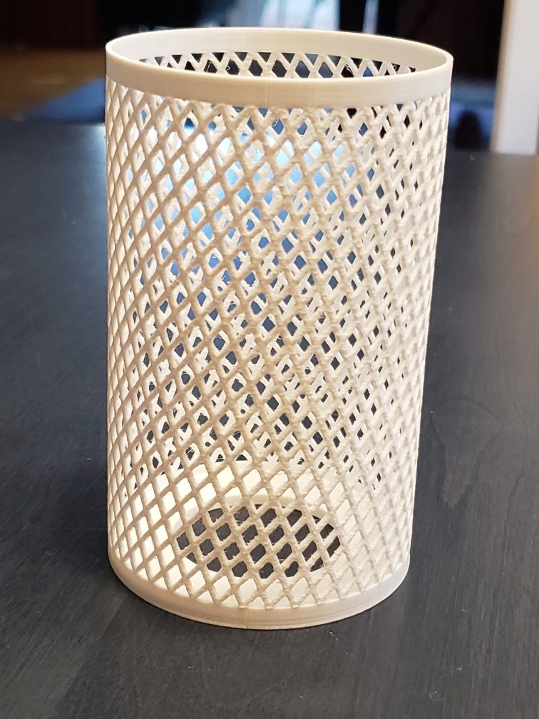
This project started out as a parameterized cross-hatched mesh cup of the right size to hold a soda can, for practice with the OpenSCAD software. A set of spiral arms is extruded from the base with a twist, and a second set of spiral arms with opposite twist overlaps the first set. I also put a hole in the bottom so the can could be pushed out from the bottom. It was a printer torture test, having to put millions of tiny dollops of plastic layer upon layer, but it came out satisfying. With a 67 mm inside diameter, it holds a can loosely.

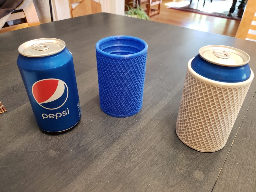
With a cold can inside, it felt nearly as cold as the plain can. I supposed it might as well also insulate the can like a cool version of one of those thick foam things, so that it might actually have some value. I added solid walls and ribs inside. The ribs reinforce the wall, which can comfortably be just 1 mm thick. The ribs also keep the walls from touching the can to form an insulating air gap with restricted air circulation. I retained the decorative cross-hatch texture on the outside, although it also lends some additional strength.

I used the Cura slicing software to convert the STL file to G-Code for printing with a layer height of 0.2 mm. On the print shown above on the right, the bottom curled up from the bed a little because my nozzle was a hair too high. I had also reduced the inside diameter to 66.5 mm and found the fit to be ideally snug. This goes to show how close the tolerance is; only 0.5 mm makes the difference between quite loose and quite snug.
I noticed that if the wall is widened to 1.5 mm thick, and Cura is told to slice with a single wall outline (Wall Line Count = 1), then the wall becomes two very thin concentric shells with sparse infill between them. That amounts to a second air layer for even better insulating properties. The blue print shown above has was made this way.
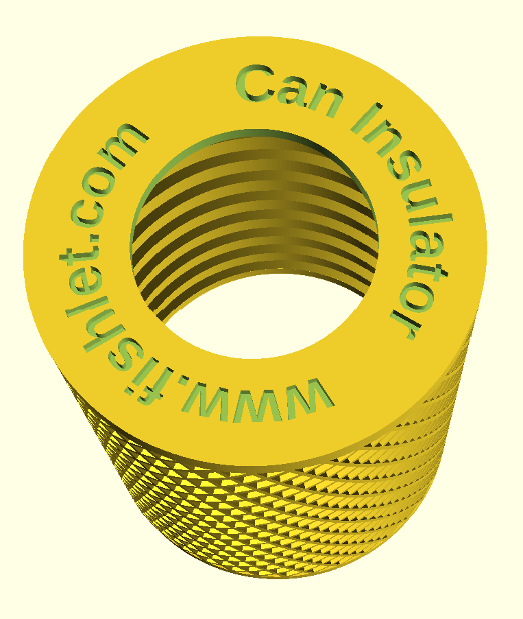
Finally, I thought the bottom of the can was begging for some text to be engraved on it, so I implemented a radial text module for OpenSCAD. OpenSCAD is currently weak in this area, as there is no way to query font metrics, so it’s impossible to find the widths of individual characters as needed to space them out proportionally. The first result using a naïve constant rotation angle approach looked terrible — characters like i and W very much need significantly different spacing.
I found a third party library developed by Alexander Pruss in 2018. It’s basically a giant table of font metric data that can be imported into OpenSCAD and some functions to look up detailed information on individual characters. To this library I added an extra function that gets the horizontal character offsets of each character in a line of text all in one go, which is far more efficient than retrieving the information one character at a time.

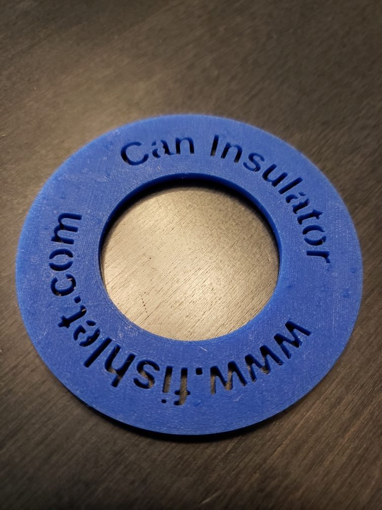
I printed the can insulator above with text engraved 2/3 of the way through the bottom. That was fine, but then I wondered about engraving the text all the way through. The problem is that certain glyphs contain holes where the center of the holes would be detached so they would fall out if printed. I was able to solve this problem by skewering those characters with vertical lines down the middle, and incorporated that feature into my radial text module. Some of the characters in question are “ABDOPQRabdegopq”, but I tried to include support for the Extended Latin code set. The percent sign (%) is an outlier. Here is a partial print I used to test radial printing with hole support.

The code for printing radial text is available in this repository:
https://github.com/curtmcd/OpenSCAD_Lib.git
and consists of
radial_text.scad
fontmetrics.scad
fontmetricsdata.scad
Note: this code uses function literals, a feature requiring OpenSCAD 2021.01 or later.
This can insulator is extensively parameterized with ~19 settings. Not only can the dimensions of different cans be accommodated, but details about the borders and texture can be tuned, as can the radial label text, font face and font size. When using OpenSCAD to open the file, be sure to check out the customizer window.
This object is available on Thingiverse here:
https://www.thingiverse.com/thing:5041806
including all three of the needed .scad files and the rendered STL for a standard U.S. 12 oz (355 ml) soda can.